Prototype
This was an optional step to ensure our design was working and to avoid potential problems once the manufactured PCBs arrived. I did some quick breadboard tests with our design, which gave us more confidence in our design.
The Breadboard Stage
Here's a picture of the prototype I built at home. I was mainly testing the
Audio Amplifier, so it doesn't include the AM Demodulator, which would have only been
an additional 5 elements. One thing to note is the two yellow wires at the top are
also disconnected in this image since the SSB demodulator wasn't being tested.
I connected the board to a Bluetooth receiver with a 3.5mm breakout connector, which
let me test an audio output without the chance of frying a directly connected phone or
laptop. Since our potentiometer for volume control hadn't arrived yet, I used a suitably
large resistor to mimic various volume levels.

SSB Demodulator
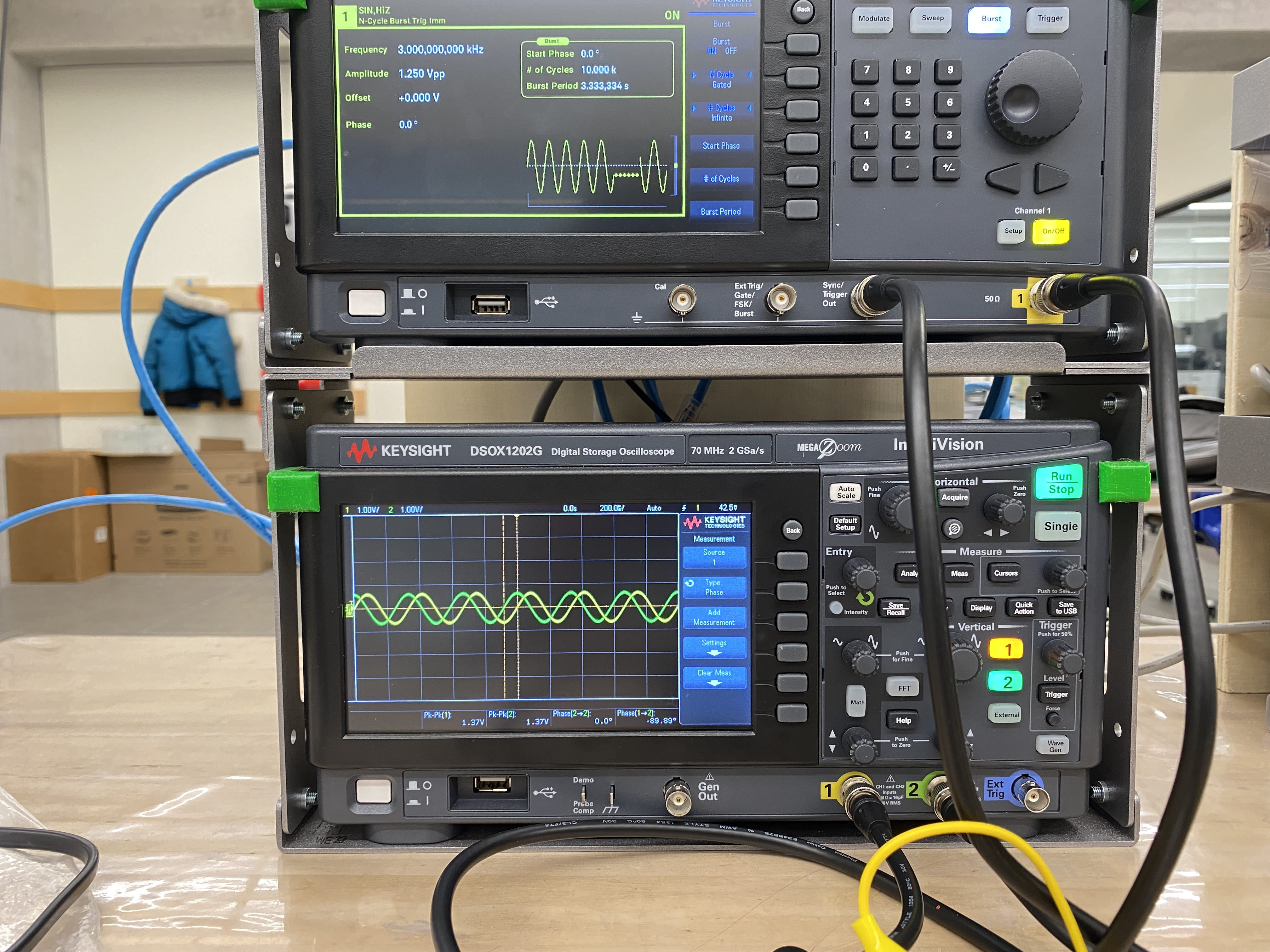
I wasn't entirely familiar with operating this specific oscilloscope at the time, so
it was a gradual learning experience before we captured testing results on the PCB.
I also didn't originally know
that the oscilloscope had a built-in feature to save images to a USB drive, so I
used my phone to take pictures this time.
The
testing ![]() page has more informative images than the ones I captured here, but from these,
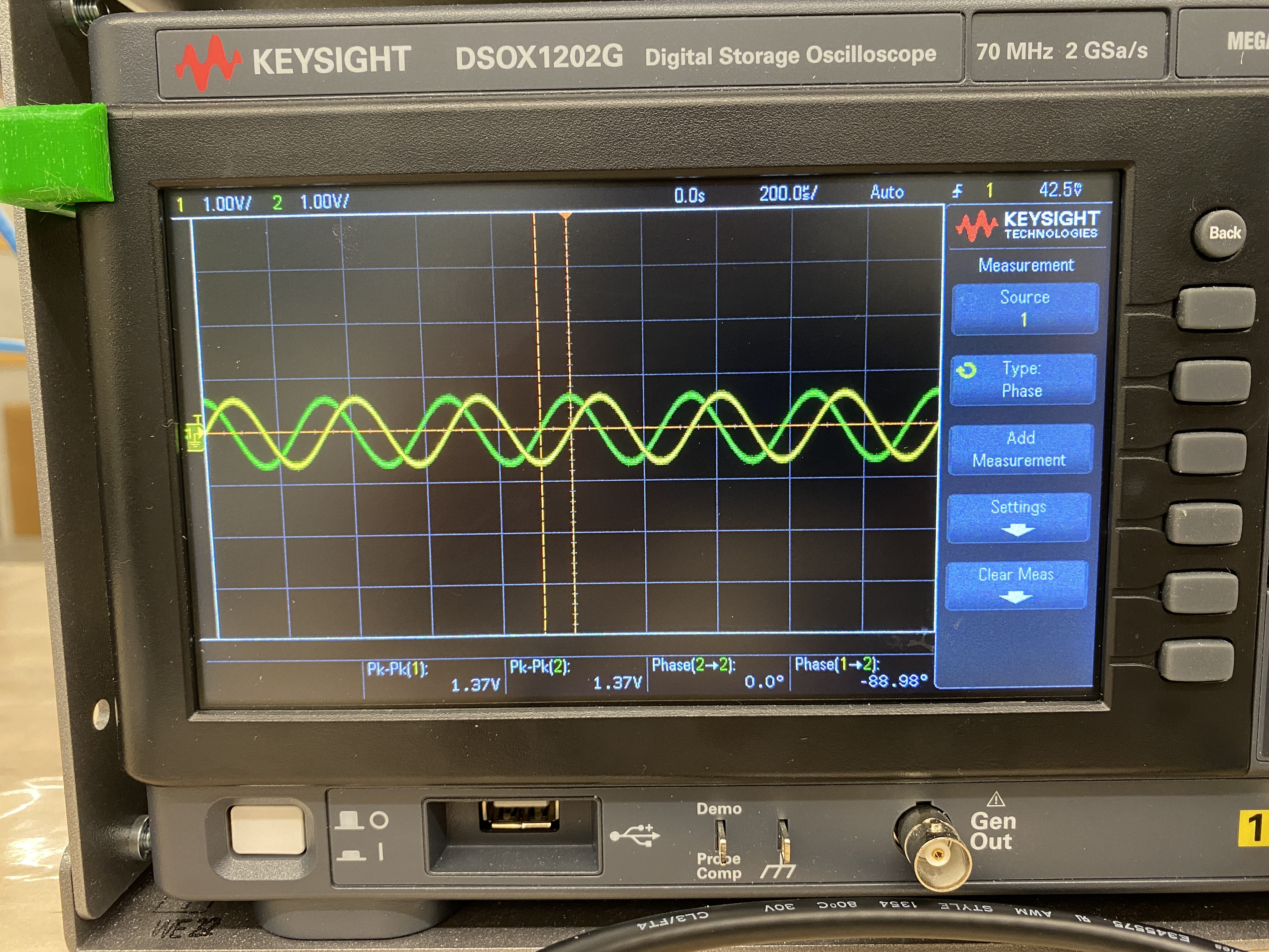
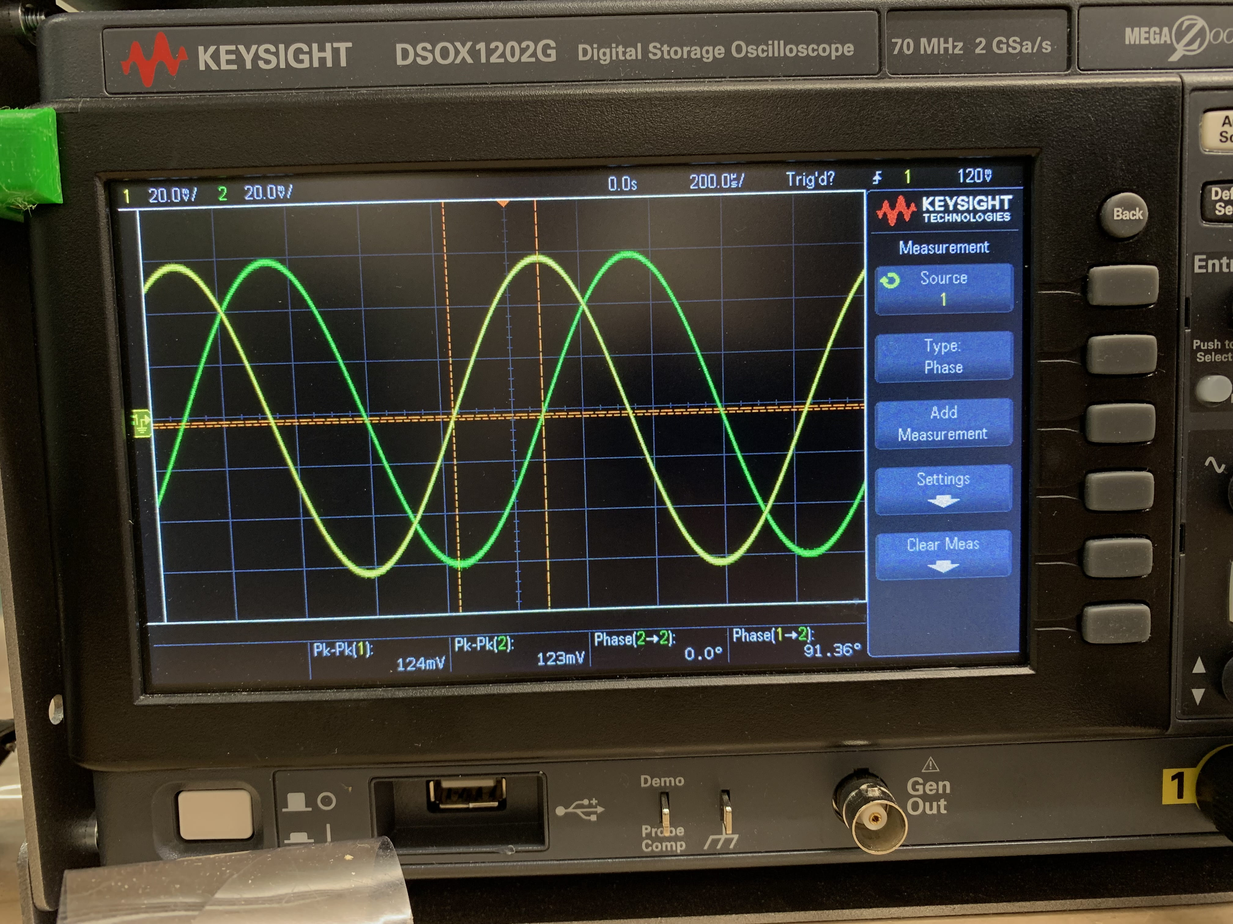
we can prove that our design achieves a 90-degree phase shift between the I and Q
signals, as expected.
page has more informative images than the ones I captured here, but from these,
we can prove that our design achieves a 90-degree phase shift between the I and Q
signals, as expected.
AM Demodulator
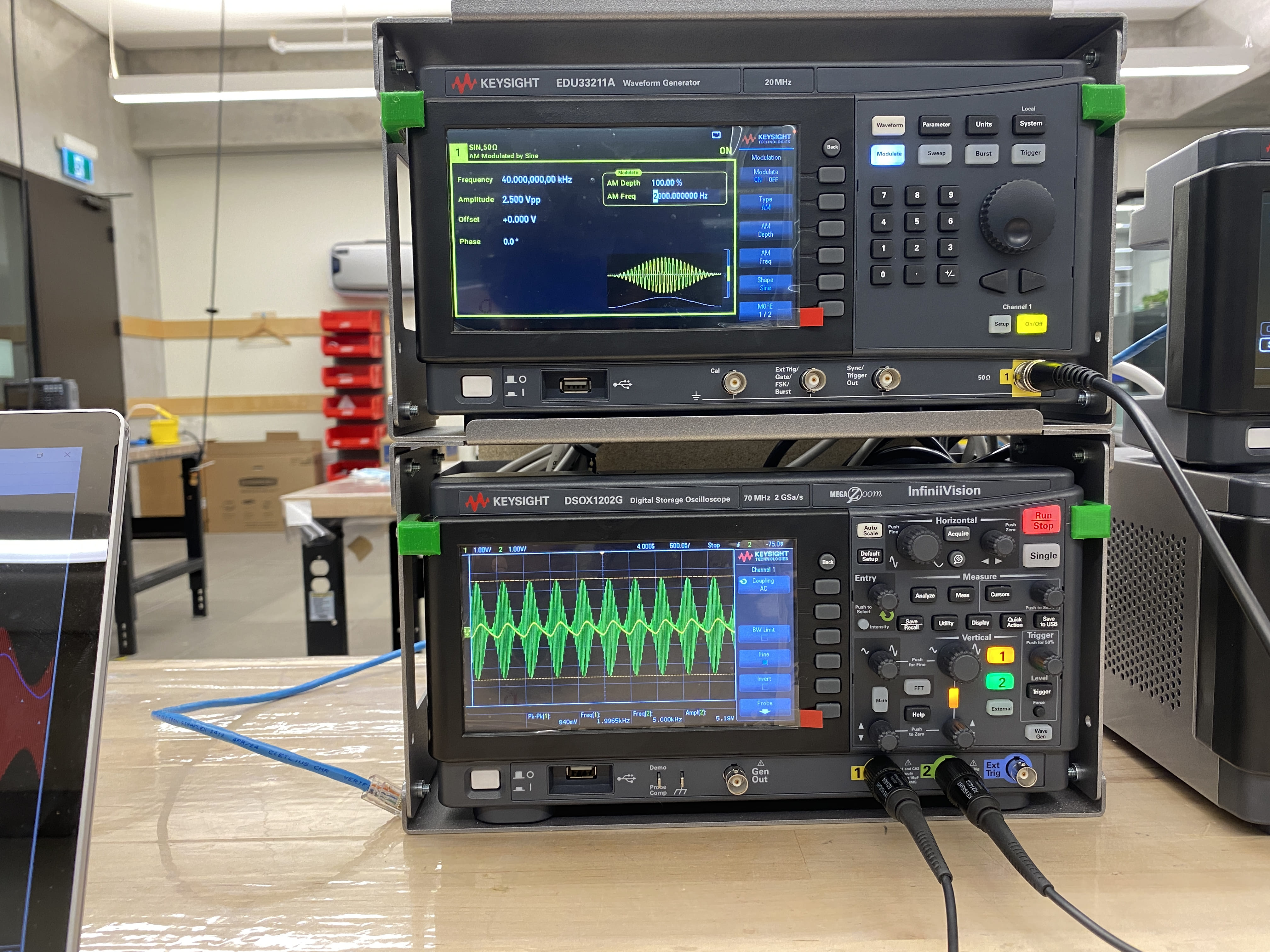
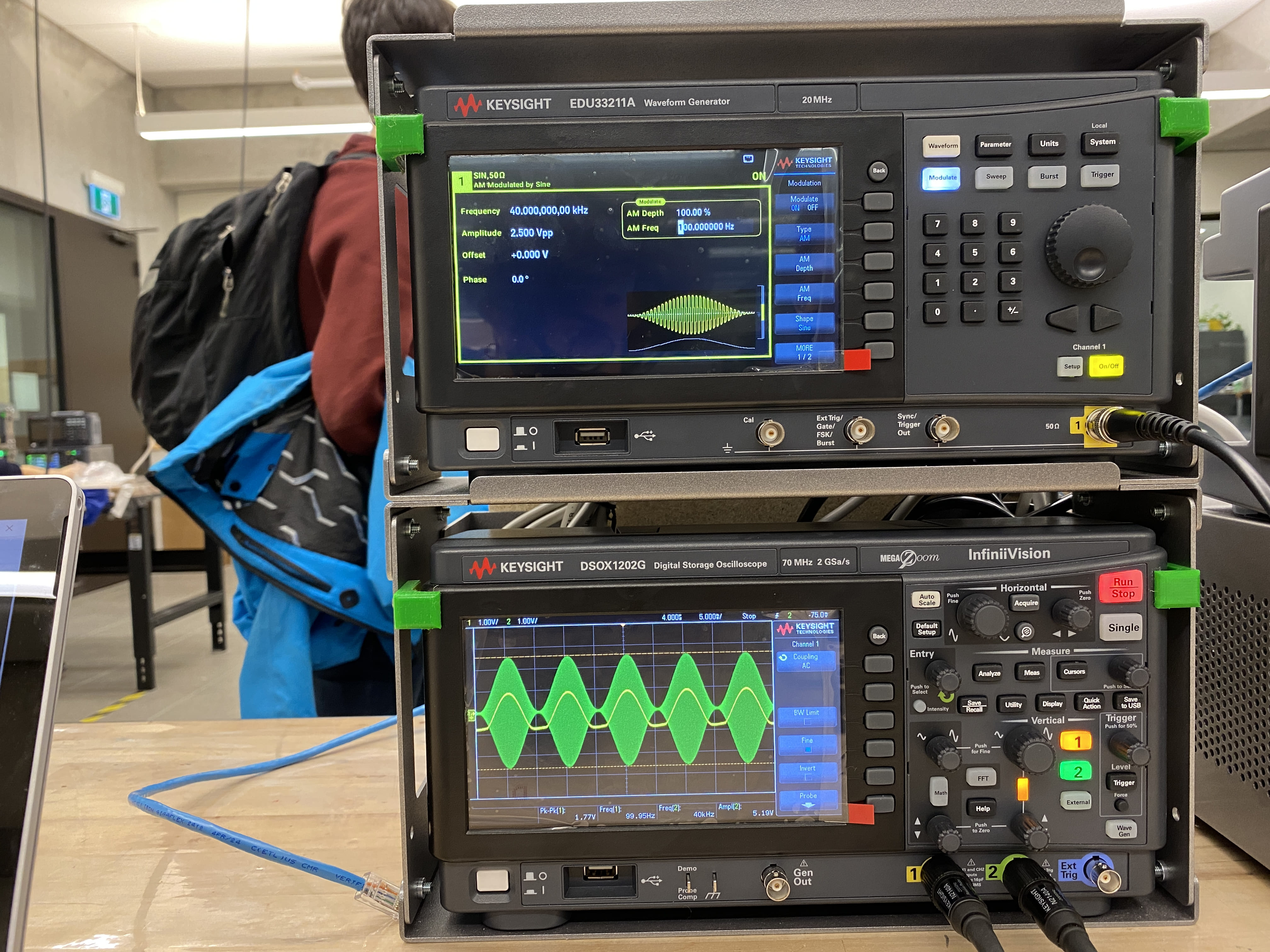
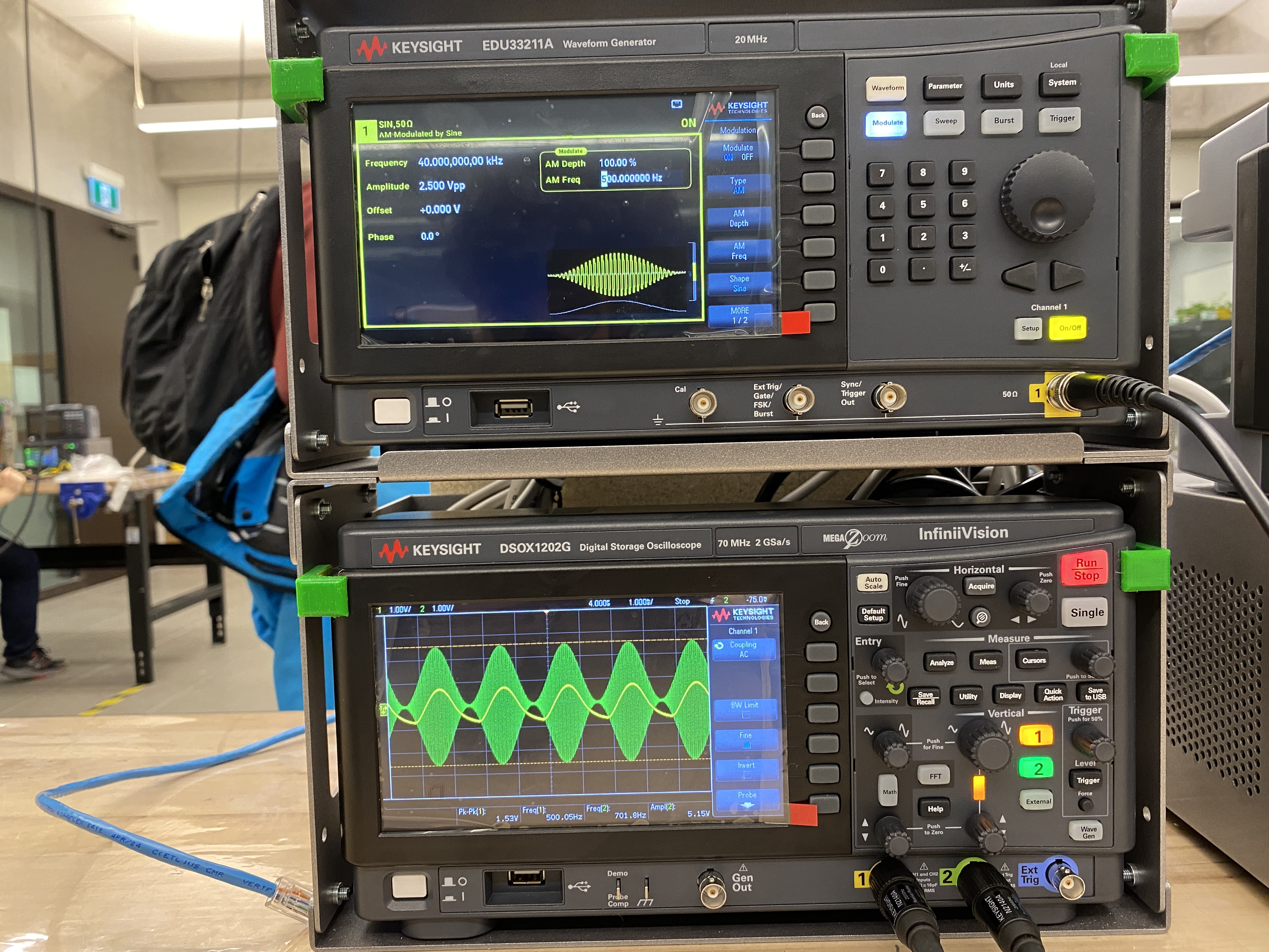
This is where we started to see problems in our design. Our AM demodulator was clipping the bottom of our signal for lower frequencies. The output was also smaller in amplitude than the input at higher frequencies. We kept it was it was, because our design *mostly* supported both 40kHz and 100kHz carrier signals.
Audio Testing
To my surprise, the output was especially loud for such a small amplifier, and the audio quality was acceptable.
Moving On
We waited a few more weeks after prototyping to receive our boards, then immediately moved on to assembly.