Testing
The last step in the design process. Ultimately the most critical as well,
as it determines just how much of the months of work was successful while highlighting
what may have gone wrong.
As serious as the previous statement sounds, you're allowed to make mistakes in ECE295.
The project is designed to mimic the industry, which also isn't invincible to mistakes.
By making mistakes here, we learn from and overcome them, preparing us to overcome
challenges in the future (and in the industry).
The Testing Setup
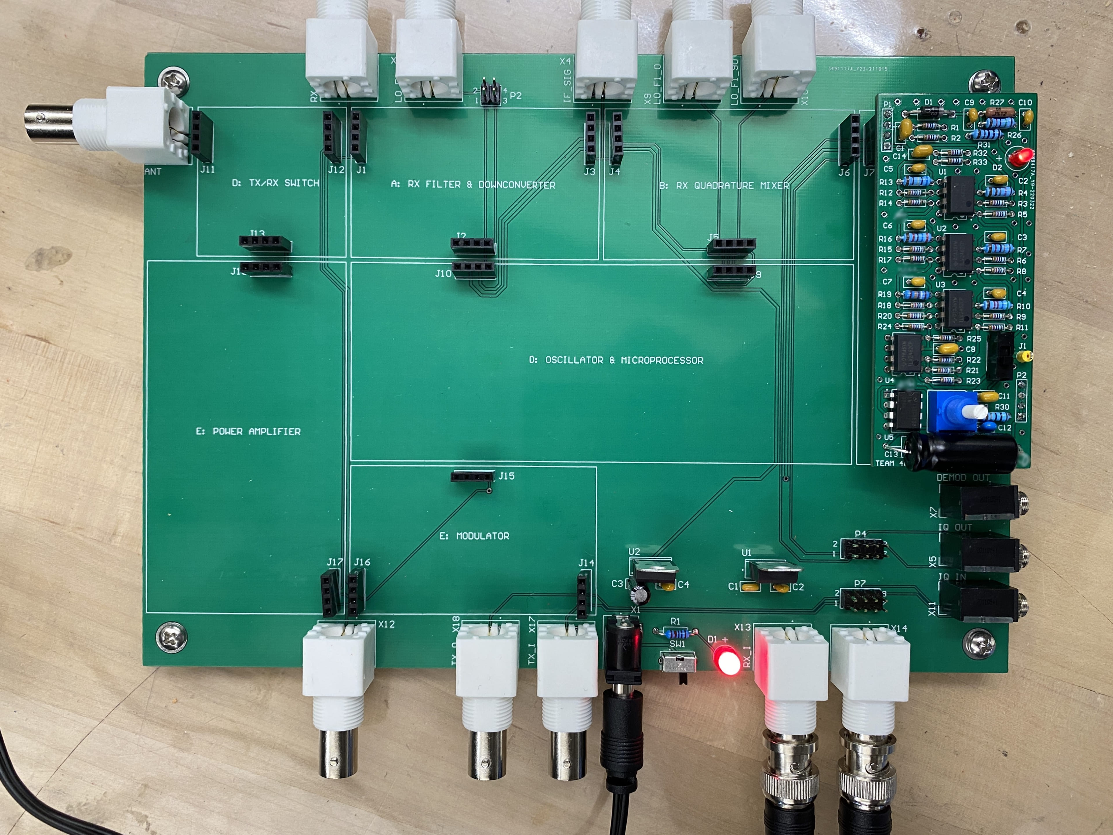
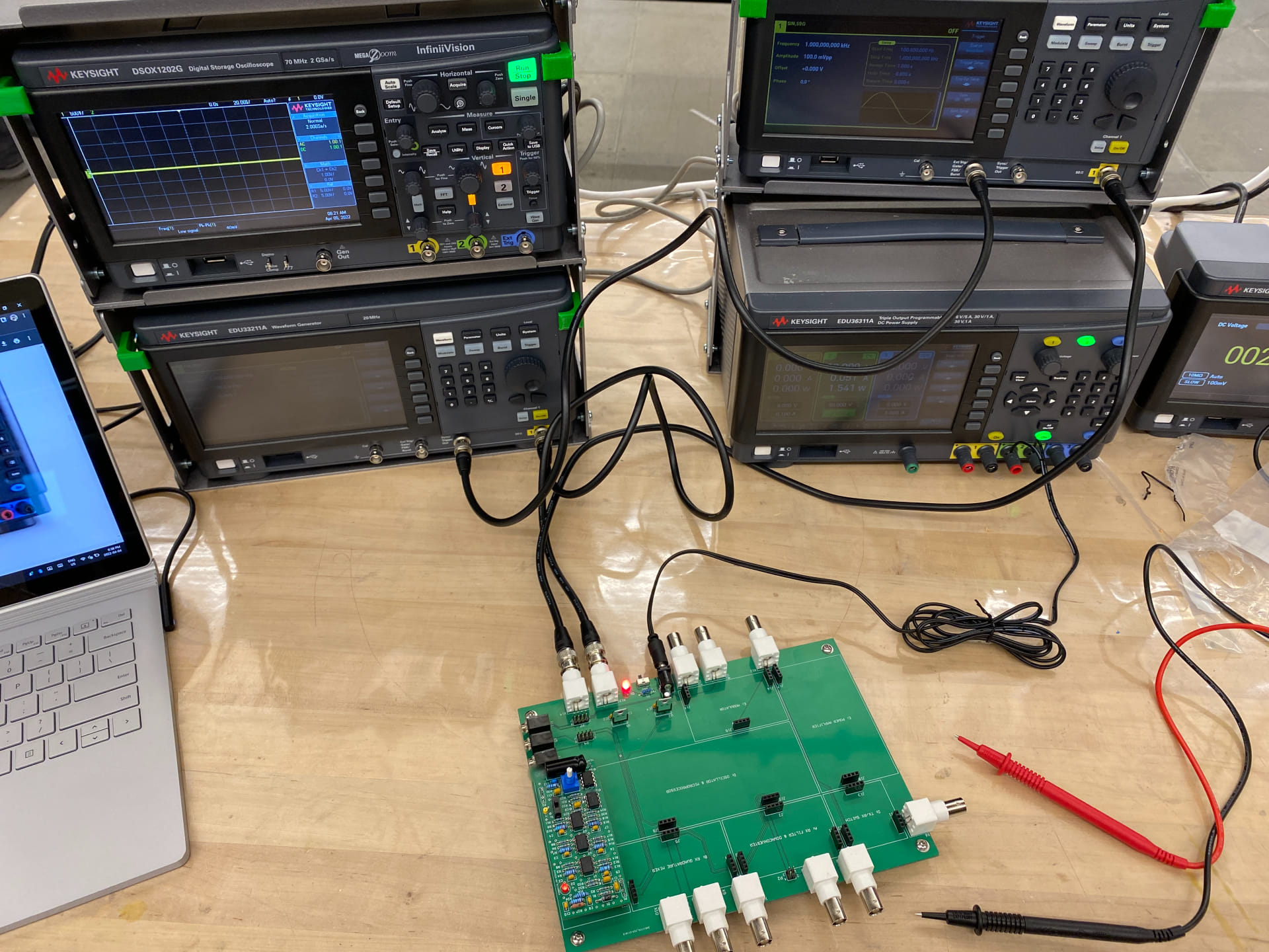
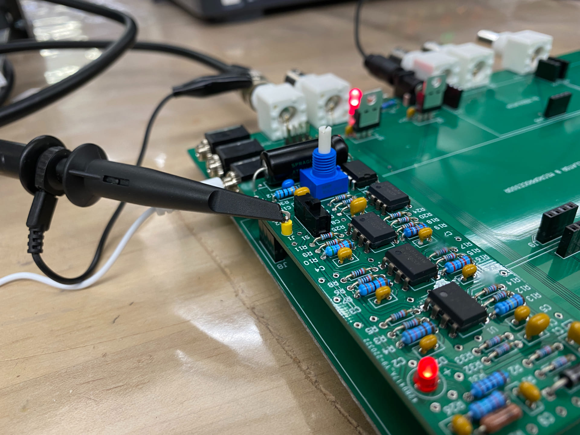
To test our design, we placed it on the ECE295 motherboard. It has BNC connectors for various input and output signals, a 3.5mm audio output, interfacing and a power supply for all subsystems. The testing equipment included a Digital Storage Oscilloscope, Function Generators, a DC Power Supply, and a Digital Multimeter.
The motherboard was connected to two synchronized function generators which produced identical signals 180 degrees apart. This was mainly used to test the SSB Demodulator, which would ideally modify the signals to be 90 degrees apart if it were to work correctly.
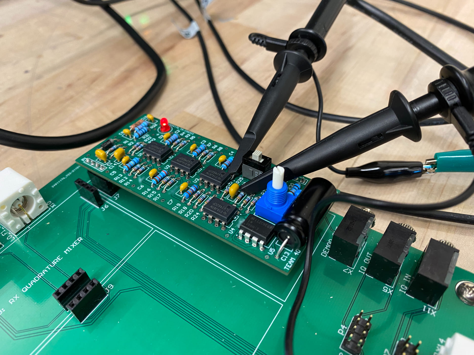
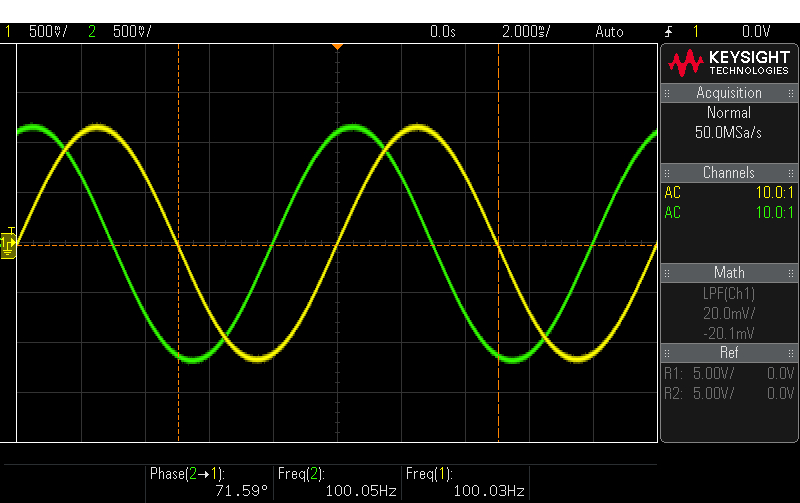
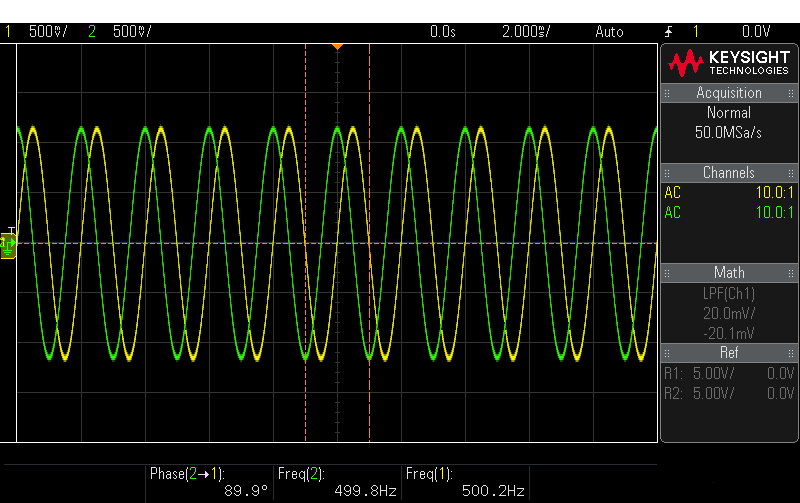
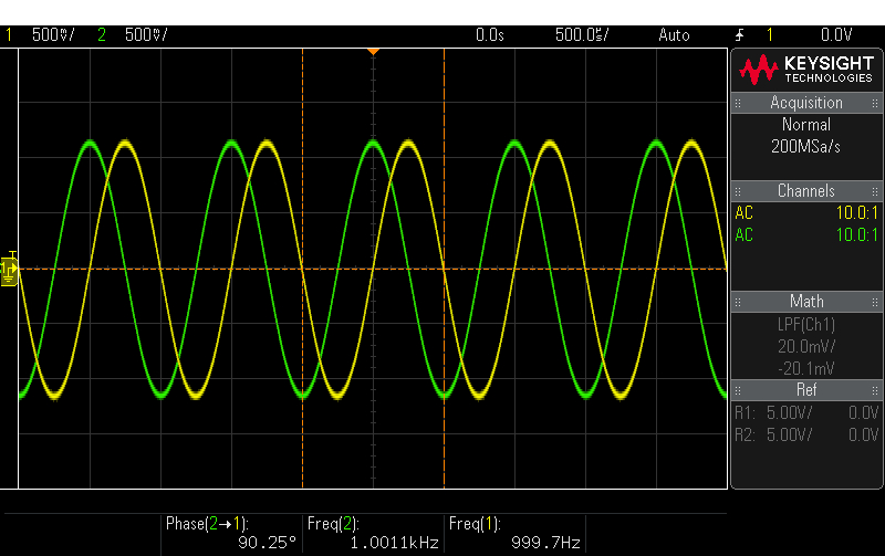
SSB Demodulator Testing
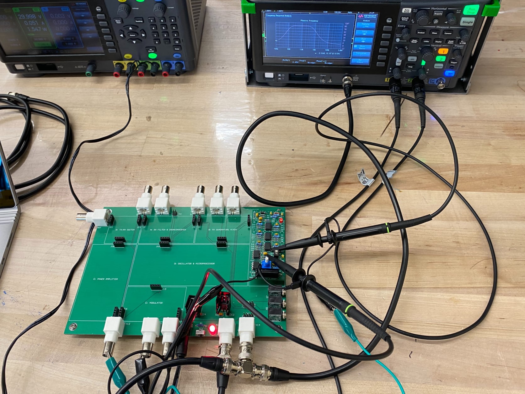
The target specification for SSB was to produce a 90° ± 12.5° phase shift between the I and Q
signals. After hooking up the oscilloscope's probes to the outputs of the SSB Demodulator and connecting its
generator output to both the I and Q input of the motherboard, we used the oscilloscope for Frequency
Response Analysis of the board.
The circuit produced a clean phase shift of about 87.9 degrees (clearly within the ± 12.5° error margin)
between 250Hz and 3.6kHz, as expected during the design phase. We then measured phase at various frequencies as shown
in the pictures below.
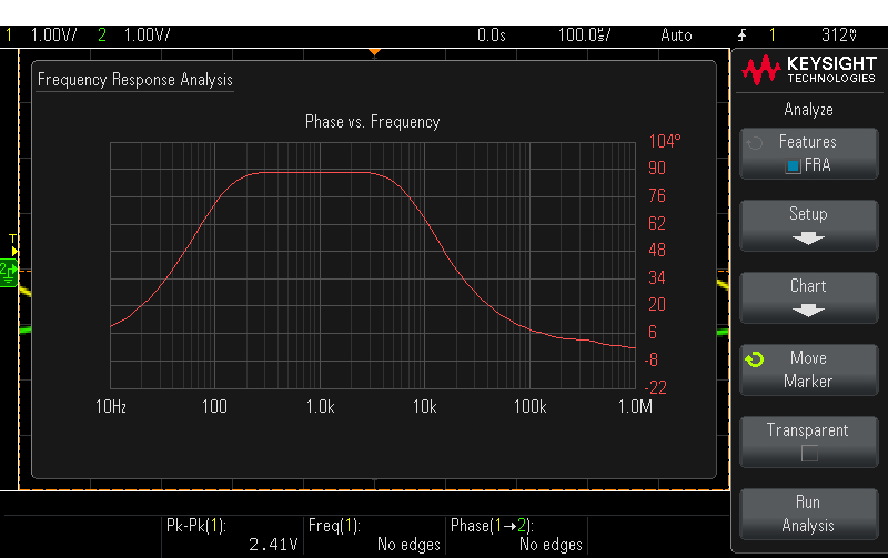

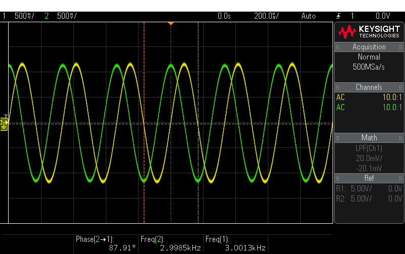

The above confirmed that our design worked within the expected range. Unfortunately, by design, the phase shifting didn't work all the way down to 20Hz (the lowest audio frequency), but since our audio range was already limited to 0 - 3kHz by the design requirements, perfect audio quality was not achievable.
AM Demodulator Testing
The board's testing point was used to look at the output of the AM Demodulator.
Using one function generator to input an AM signal into the I input of the motherboard,
we tested the AM demodulator at both 40kHz and 100kHz carrier frequencies.
This test wasn't as satisfying or as successful as the SSB Demodulator. Our AM Demodulator
was the same as during the prototype phase, so it couldn't keep up with tracing the higher audio
frequencies and clipped the bottom of the lower audio frequency signals. The testing results
can be found below.
A combination of issues led to an imperfect AM Demodulator. The diode
was not particularly efficient, which we could have overcome with a more expensive component
or with a precision rectifier circuit. However, the main issue was the difference between the carrier
and message frequencies. Normally AM radio is between 500kHz - 1.6MHz, which is far more headroom
to demodulate than 40kHz or 100kHz down to 0 - 3kHz (A limitation set by the project design requirements).
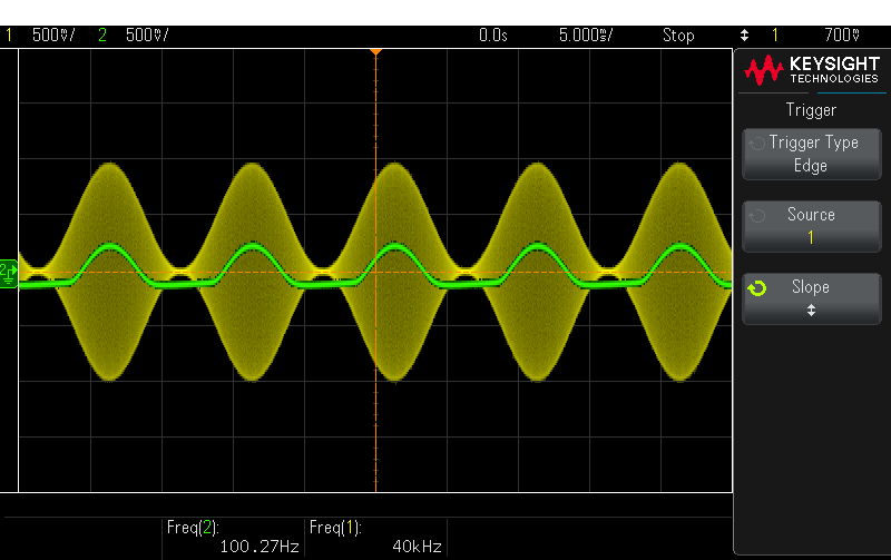
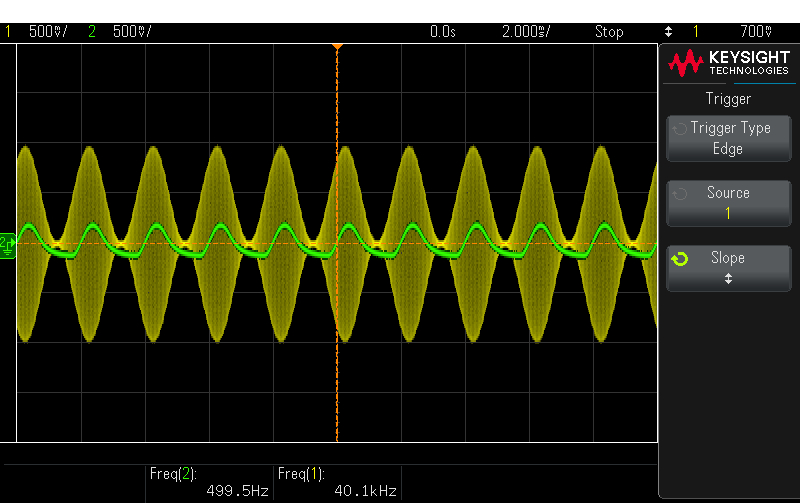
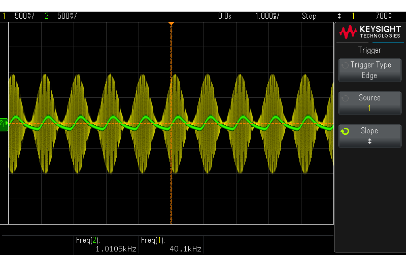
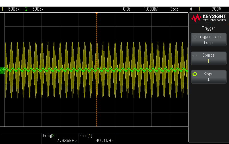
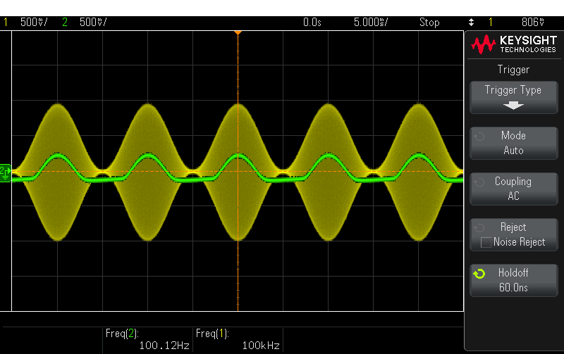
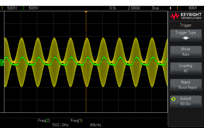
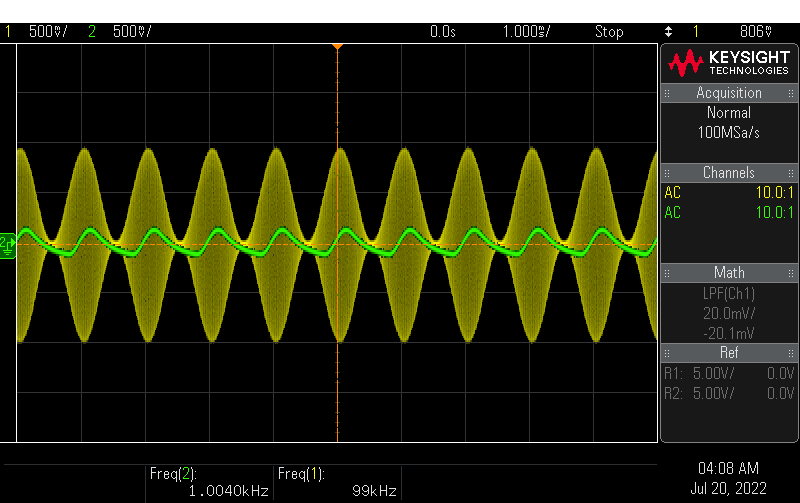
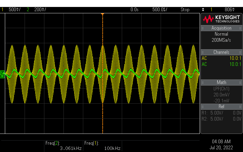
Top Row - 40kHz carrier frequency
Bottom Row - 100kHz carrier frequency
at 100Hz, 500Hz, 1kHz and 3kHz message frequencies
Audio Amplifier Testing
Here are two videos to show audio testing. The first one tests sound quality, and the second tests volume control.
I think we can safely call the audio testing a success since we're ignoring sound quality.
Systems Integration Day
At the end of the project, all the teams with working boards came together to integrate their subsystems and create a working SDR. Our team participated, and our board was able to provide an audio output for an SSB signal received from another ECE295 SDR. By no surprise, our AM Demodulator did not work well enough to be operational.
The End?
With testing done, all that was left was to showcase our PCB and testing results
in a final presentation. I would've put a link to our slides here, but this website
is a suitable alternative to showing off our entire design process and most of what
I've learned from it. If you made it this far, thank you for reading thus far!
You can find more details about this project as a whole
here ![]() .
.